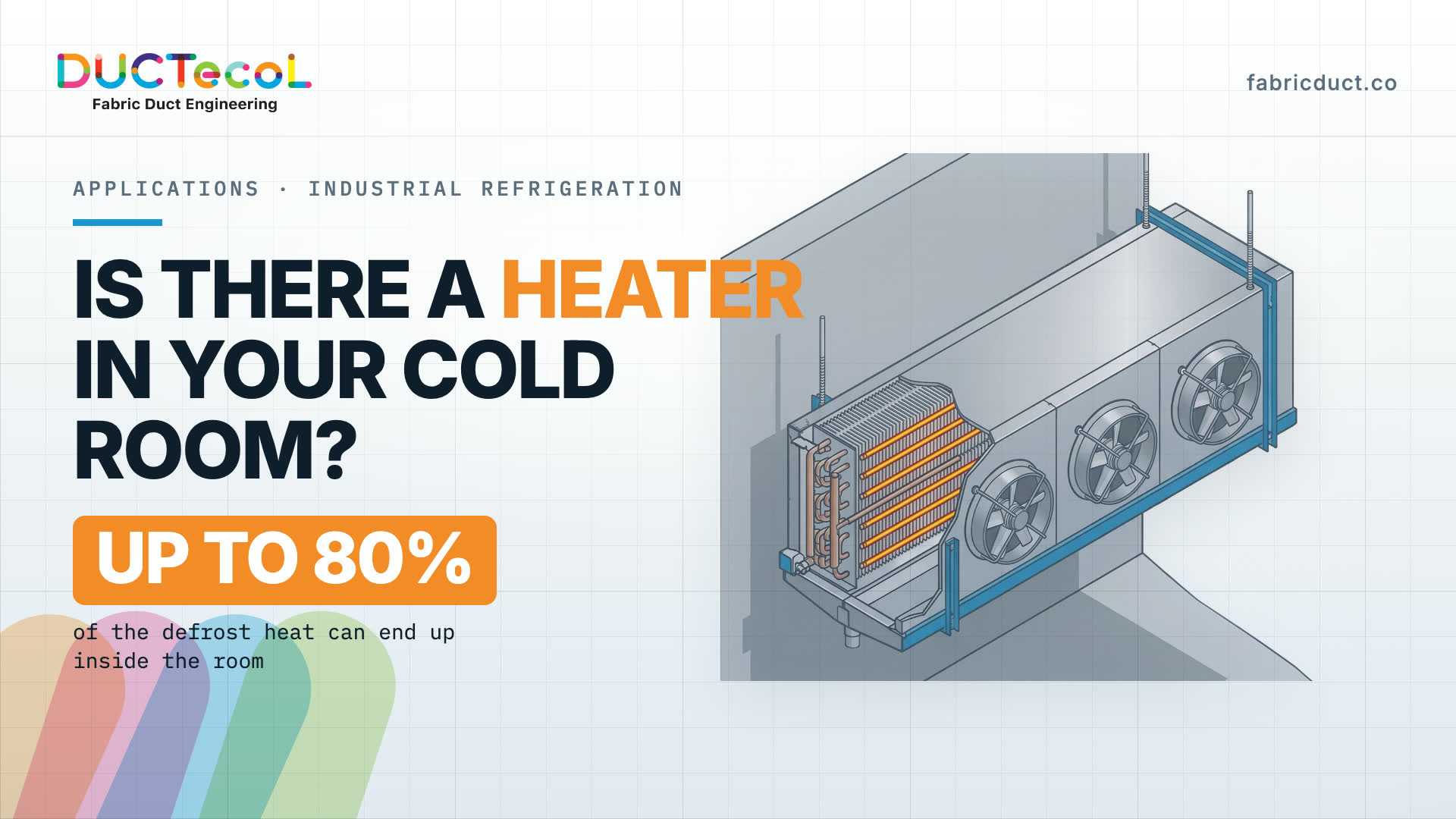
The controller reads one point, almost always the evaporator return, and the plant treats that number as the condition of the whole room. The product lives in the rest of the volume, where throw, stacking and defrost heat decide the real temperature.
A cold room does not have a temperature. It has a map.
The number on the control panel belongs to one sensor, usually at the evaporator return. The product lives in the rest of the volume, where three things set the local temperature: how far the air travels, what the load blocks, and how much heat the equipment releases into the space.
ASHRAE puts the requirement plainly in Chapter 21 of the Refrigeration volume: the air moved by the fans has to reach every part of the room uniformly. That is a design result, not a byproduct of hanging a unit cooler on a wall.
Why the jet dies before it reaches the far wall
A unit cooler does not distribute air. It throws a jet. The fan openings discharge parallel streams that merge, within a few opening diameters, into one jet aimed down the room, and that jet drags the surrounding air with it. That entrainment costs it velocity.
ASHRAE Fundamentals describes the decay of a free jet with a compact expression:
V_x = K * V_0 * sqrt(A_0) / X
V_0 is the discharge velocity, A_0 the effective discharge area, X the distance from the outlet and K a constant of that outlet. Velocity falls as 1/X: at twice the distance, roughly half the velocity. If throw was never checked against the real length of the room, the far end receives nothing. The Refrigeration volume states the consequence in its unit cooler selection guidance: ignoring throw and unit location produces “areas of stagnant air and hot spots in the refrigerated space.”
The second obstacle changes every day
The load is the other half of the problem, and it changes every shift. Air does not pass through product; it goes around it. Behind each stack, on the face away from the equipment, a pocket of air sits on the floor and stops renewing. Chapter 21 is blunt: an elaborate distribution system is worth nothing if the stacking pattern blocks the airflow.
That pocket has a price in product. Chapter 22 reports that the shelf life of fresh meat peaks at 29 degrees Fahrenheit (minus 1.7 Celsius) and is cut in half when the meat is held at 36 degrees Fahrenheit (2.2 Celsius). A spread of 7 degrees Fahrenheit inside one room costs half the shelf life of whatever sits in the warm end.
First family: the duct is the diffuser
The first family of textile ducts attaches to the discharge of the unit cooler or air handler through a collar and turns a concentrated jet into a path: the air enters the fabric and leaves distributed along the whole room.
The consequence that matters is velocity. Because the discharge area is the whole surface of the duct rather than a fan opening, the air arrives over the product slowly. Chapter 30, on meat products, warns that strong drafts and high-velocity airstreams striking the product cause local overdrying and non-conforming output.
One point is often misunderstood: inside a refrigerated room the textile duct is not insulated, and does not need to be. Supply air and room air sit at practically the same temperature, so there is no thermal difference to insulate against. The demanding part is the material, a technical textile rated for the minimum temperatures of industrial refrigeration.
In a food room the system also comes down in sections at its zippers, is washed in plant and returns with a technical report.
The heater that runs inside your freezer
Any evaporator working below freezing accumulates frost. Moisture from the product, from infiltration and from door operation freezes on the coil, bridges the fins and closes the air passages. Capacity falls. That is why the defrost cycle exists: the controller stops the fan, cuts cooling and energizes the heater rods inside the fin block.
The industry already treats that heat as a liability. Chapter 14, on forced-circulation air coolers, recommends delaying fan restart until the coil surface temperature approaches its normal level, so the room is not heated unnecessarily after defrost.
But a stopped fan seals nothing. The discharge opening stays open, the air warmed by the heaters is lighter, and it leaves through the top of that opening into the room. The same chapter, under frost control, puts a number on it: depending on the method, as much as 80 % of the unit defrost heat load can end up inside the enclosure, a load not normally carried into the room heat gain calculation. It shows up on the bill, not on the sheet.
The same heat is paid for twice
First as the electricity drawn by the heater rods, then as the compressor work to pull that heat back out of the room. The FAO reaches the same conclusion in Animal Production and Health Paper 92, on meat cold store operation: defrosting is an expensive operation that consumes energy already incorporated in the store, and the lower the storage temperature, the more the heat load is affected. Written as a balance, the real energy of the cycle is:
E = E_defrost + Q_leak / COP
E_defrost is the heater electricity, Q_leak the share that reached the room, COP the system coefficient of performance. In freezing COP is low, so removing each unit of leaked heat costs a meaningful fraction of what it cost to produce.
Second family: a damper that gravity closes
The second family closes that leak with no electronics, no actuators and no maintenance: a short textile sleeve installed on the fan discharge. While the fan runs, air pressure keeps it inflated and open.
When the controller stops the fan for defrost, the pressure disappears and the sleeve falls under its own weight, covering the opening and cutting the path the heat escaped through. The heater energy stays inside the housing, where the ice is, so the cycle concentrates and finishes sooner. That protects product as well: Chapter 14 warns that an excessively long defrost cycle can drive an unacceptable rise in product core temperature.
Two families, one design
Distribution and defrost are not two separate products. One spreads the air while the equipment cools; the other seals the discharge while it defrosts. Both are sized for the geometry and load of one particular room.
That sizing is not a catalogue exercise. ASHRAE says so explicitly: guesses and rules of thumb are not an acceptable basis for selecting equipment with the right airflow. Before any fabric is cut, the room is simulated with the real load and stacking pattern of the project, so velocities, temperatures and air path are known in advance.
Frequently asked questions
Does a textile duct inside a cold room need insulation?
No. The supply air and the room air are at practically the same temperature, so there is no thermal gradient to insulate against, and an insulated duct would add weight and cleaning difficulty with no benefit. The demanding requirement is the fabric itself, which has to remain serviceable at the minimum operating temperatures of the room.
Does the 80 % figure for defrost heat apply to every installation?
No. ASHRAE states it as an upper bound that depends on the defrost method, so electric, hot gas and air defrost do not behave alike. The value of the figure is that it sets the order of magnitude of a load that is usually absent from the room heat gain calculation entirely.
How is the hygiene of the air system documented in a food plant?
The textile sections are separated at their circumferential zippers, taken down, washed industrially and reinstalled, and each unit returns with a technical report of the cycle. That report is what turns an unverifiable claim about duct cleanliness into an auditable record.
The room already has a unit cooler. Does it have to be replaced?
Normally not. Both families connect to the existing equipment: the distribution duct to its discharge through a collar, and the defrost sleeve to the fan outlet. What changes is how the air is delivered and what happens to the discharge opening during defrost, not the refrigeration plant.
The decision criterion is not the duct. It is where the temperature spread in the room comes from. If the far end of the room is warm and the equipment is sized correctly, the problem is throw and distribution, and the first family applies. If the room is at low temperature and the defrost cycles are frequent and long, part of the load is heat the equipment is putting back in, and the second family applies. Most industrial rooms are in both situations at once, which is why the two are designed together, against the real geometry and the real stacking pattern, and not chosen from a catalogue.
Request a technical sizing study for your cold room from the DUCTECOL engineering team at fabricduct.co.